Pi Zero Portable Air Quality Sensor — Construction in 10 “simple” steps.
Instructions on how to wire the RPi Sensor. This process takes ~2h for a first attempt. These are generic instructions related to the Born In Bradford project on measuring the air quality …
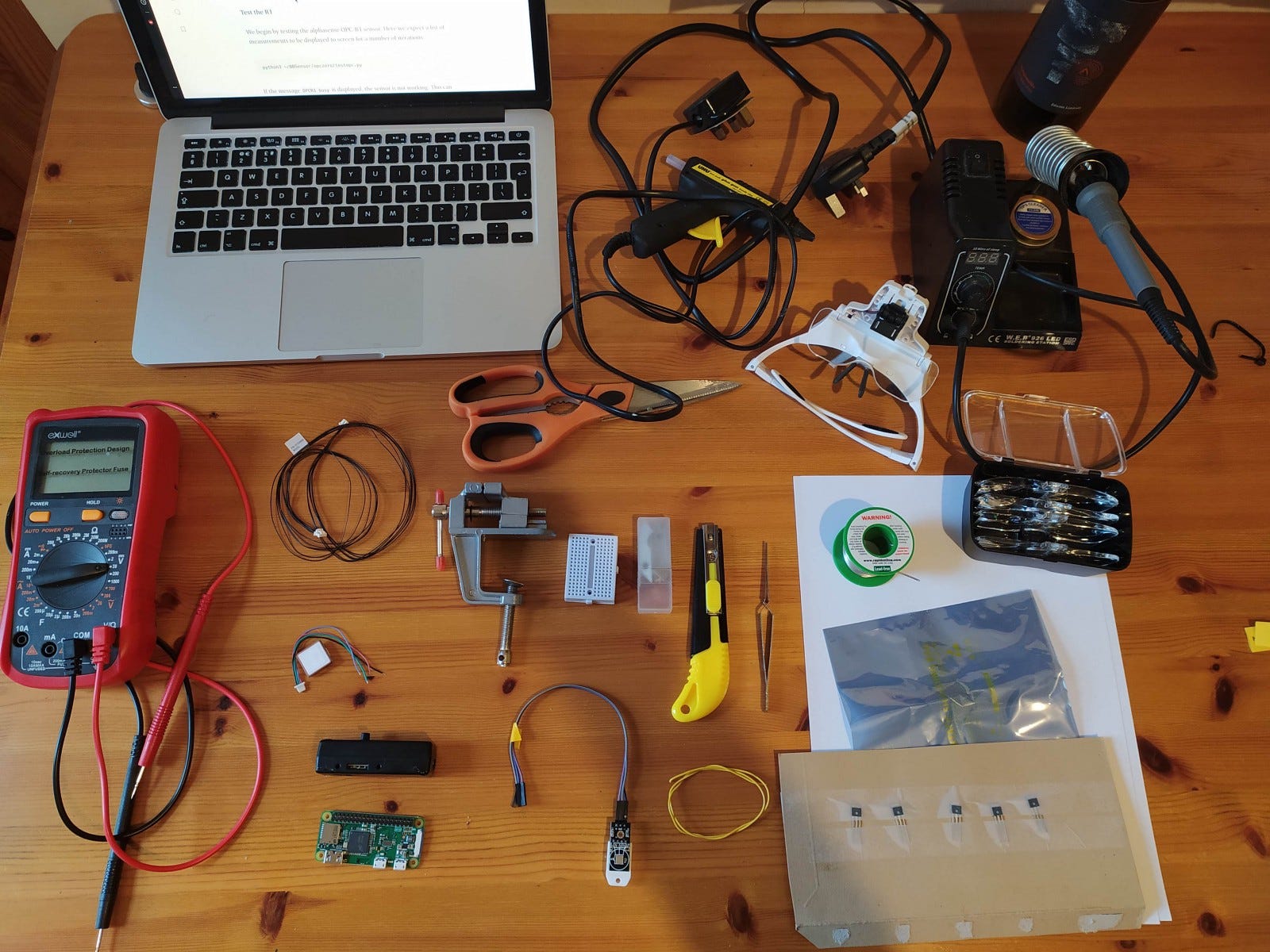
1. Gather all the components and tools
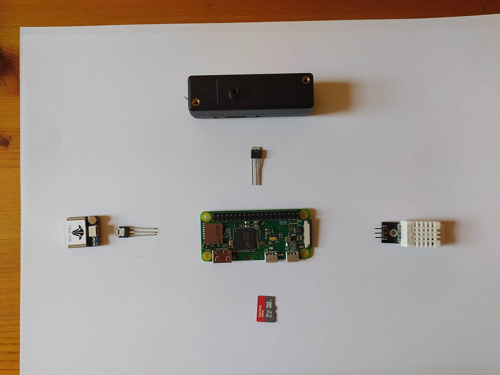
Component list:
- RPi Zero W
- Alphasense R1 OPC
- micro SD card
- 2N222 NPN transistor
- 28ohm resistor
- rx2 x 5v Zener diodes
- Rx/Tx GPS unit
- Temperature and Relative Humidity Module
Additional Equipment:
- soldering iron + solder
- glue gun
- wire stripper/sharp blade
- heat-shrink wrapping
- mountable magnifying glass
- wire
Pi Zero GPIO-pin Schematic
The following sections discuss the soldering of wires onto the raspberry pi itself. These may refer to a GPIO number (bold), Pin number (small) or list the pin function (name).
2. Prepare the equipment
To save time we start by making sure everything we need is organised and available. This involves:
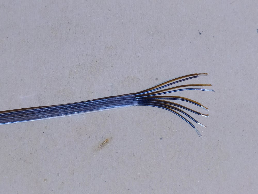
- Carefully stripping each wire
- Making sure you have each part
- Devising a method of immobilising small components
- Making sure you are using a well-lit environment with good ventilation
3. Setting up the power switch for GPS and the OPC
This controls the power to the OPC -R1 sensor and the GPS unit. Here we use a 2N2222 transistor to complete/interrupt a circuit from the 5V rails using the raspberry pi’s 3.3v digital output pins. This allows us to restart each module; turn them off at night, and stop them working if the code exits or crashes.
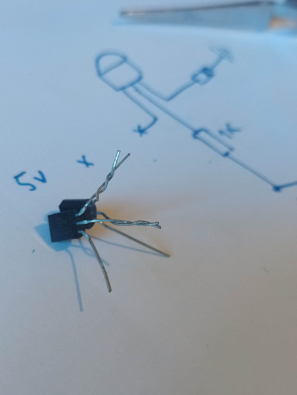
2N2222 Transistor
From the datasheet provided by Farnell —
The 2N2222 from Multicomp Pro is a through-hole, low power bipolar transistor. This NPN silicon planar switching transistor is used for switching, linear DC power supply and VHF amplifier applications.
- Collector emitter breakdown voltage is 30V at IC = 10mA, IB = 0
- Continuous collector current (Ic) of 800mA
- Power dissipation is 500mW at Ta = 25°C
- Operating junction temperature range from -65°C to 200°C
- Collector emitter saturation voltage is 1.6V at IC = 500mA, IB = 50mA
- DC current gain is 30 at IC = 500mA, VCE = 10V
- Collector base breakdown voltage is 60V at IC = 10µA, IE = 0
- Transition frequency is 250MHz at IC = 20mA, VCE = 20V, f = 100MHz
Transistor Schematics
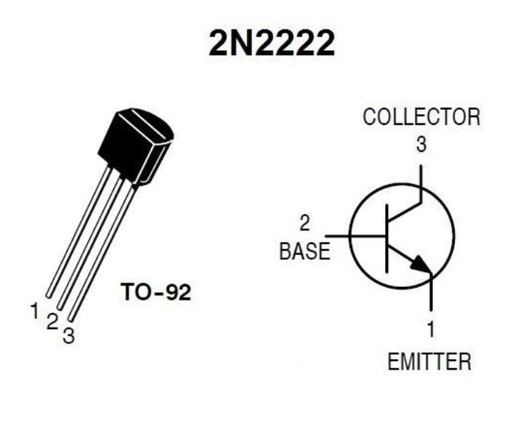
The transistor consists of three pins: a collector, emitter and base.
We think of these as a switch, completing a 5v circuit to our component of choice. The setup for this involves connecting the 5v to the + (Vin) terminal of our component, and the negative (ground) to the 2n2222 emitter leg. This forms the high(er) voltage/current circuit we will turn on and off.
We are now able to connect the collector pin to ground and our GPIO pin to the base input (see section 6). The GPIO pin now acts as a gate, which when activated completes the circuit, turning on our components.
Resistance & some basic mathematics
As we are only using the transistor as a switch, we are only concerned with the voltage and current required to saturate it (turn it fully on).
Using the datasheet above, we can see that this is a base current (IB) of 50mA at a voltage of 1.6V — This value varies depending on the transistor you are using!
Knowing this we can now calculate the resistance required to achieve the correct current to activate the switch.
Note: too high of a resistance, we only partially open the switch (limiting the output voltage). No resistor, we run the risk of melting the transistor (don’t do this!).
We know that Voltage = Current x Resistance so rearranging the equation we can calculate the size resistor we need.
( 3.3V (GPIO Pin) - 1.6V (Base) ) / 0.05 = 34 Ω
Therefore we need at least a 34Ω resistor.
Putting it all together
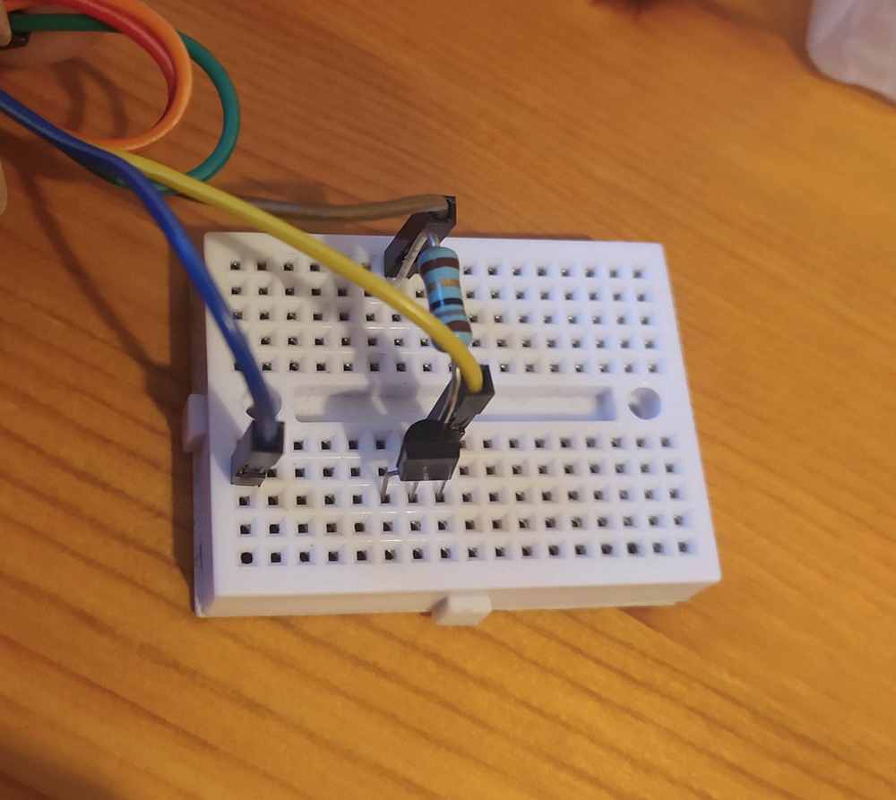
Begin by experimenting on a breadboard to ensure you have the correct orientation and that the circuit works.
Once you are happy with this we can introduce the second transistor. Here we can pair the base and connector pins of each transistor together (as in the image in the section titled “2N2222 Transistor” above). We now solder these together and connect the relevant resistor to the base pin legs.
4. Adding the GPS unit
Having established the main setup for turning on the OPC and GPS modules, we can now begin wiring them to the Pi.
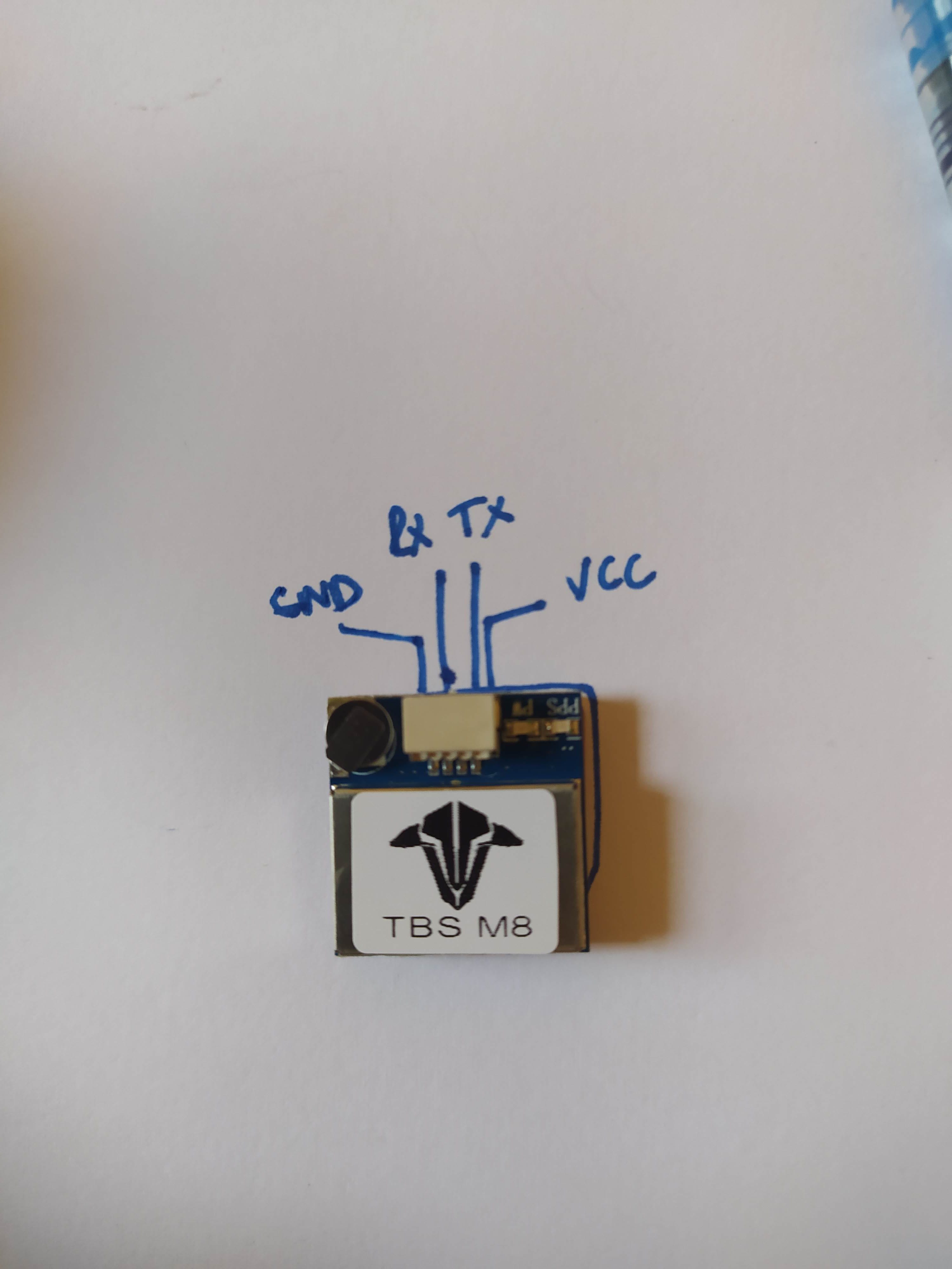
For the GPS we start by connecting the communication channels. Here we connect the RxD and TxD pins on the Raspberry Pi to the corresponding Rx and Tx outputs from the sensor. It is worth noting that these need to be switched around.
- Tx → RxD (GPIO16)
- Rx → TxD (GPIO 15)
It was found that using pins 2,4,6,8 worked well for connecting the GPS unit.
Don’t forget the ground pin will go to the emitter pin of our transistor!
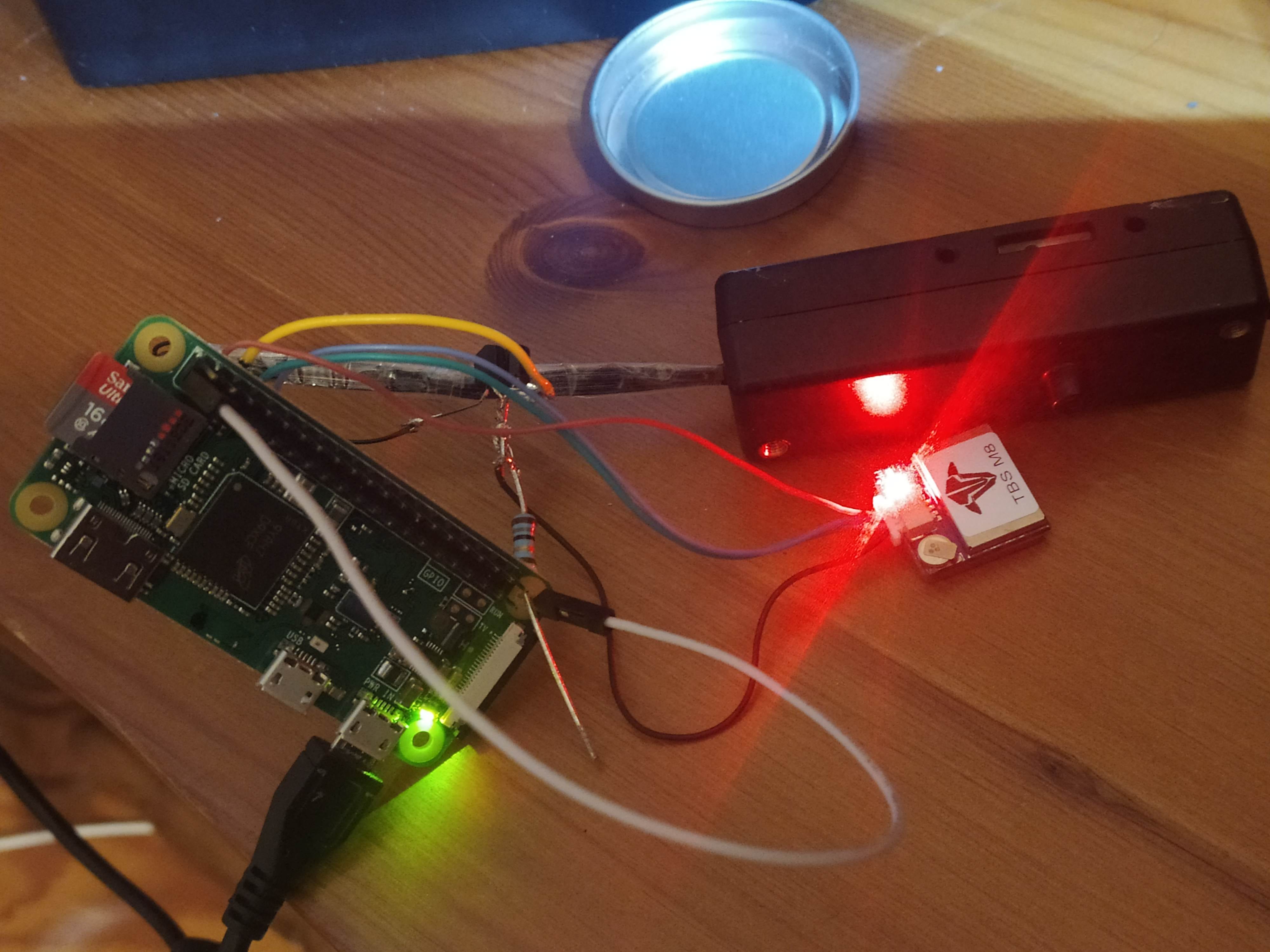
Testing the unit
To test the unit, you can connect the topmost-left pin on the RPi (3.3v) to the resistor and see if this turns on the GPS unit. This should show a bright red light. Once the unit has found locational coordinates, it will also flash a green light ~every second. The latter may require a working OS which polls the GPS unit for results and direct line of sight to the sky.
5. Connecting the OPC
Alphasense OPC-R1
It is possible to check the wires using the resistance function of a multimeter, however, it is much easier to tape them in the correct order (see left).
The pico Molex connector pins are numbered 1–6 starting on the right-hand side when the clip part of the connector is on top.
Using the RPi GPIO diagram above, we solder the pins as per the table below :
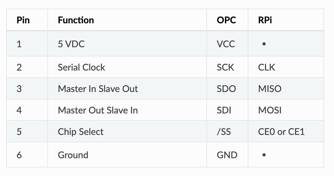
- 1 → 5v rail (Top right most pin)
- 2 → GPIO 14 — SCLK (SPI)
- 3 → GPIO 13 — MISO (SPI)
- 4 → GPIO 12 — MOSI (SPI)
- 5 → GPIO 10 — CE0 (SPI)
- 6 → ground — As with the GPS, the ground pin goes to the emitter output of the second transistor.
6. Connect the transistor to a driving pin
In theory, the origin of this does not matter — available digital pins are :
GPIO pin numbers: 4 7 8 9 10 11 14 15 17 18 22 23 24 25 27 30 31
However, for convenience, we shall use pin number 13?
7. Temperature & RH module
Finally, we need to add the temperature and relative humidity module. This can be wired as follows:
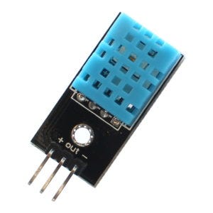
- 17 (3.3v) → Vin (+)
- 15 (GPOIO)→ Data out
- 9 (ground) → Ground (-)
Note: 4 pin devices require an additional resistor, whilst 3 pin ones (as in the image) already have this built-in.
8. Flash the Micro SD card
I suggest using Etcher for this.
9. (Optional) Boot the device and check all is working with the Bluetooth app
If you have been allowed to access the PI through Bluetooth….
Alternatively, you could run the test scripts manually and view the standard output through a terminal.